Abstract
This single-option, dual-aircraft experiment is designed to observe the structure and evolution of the inner core wind field of developing or mature hurricanes. True dual-Doppler data are obtained within 45 nmi (75 km) of the center with a horizontal grid spacing of 0.5 nmi (1 km). Three such data sets over 7 h, 2.3 h apart, are obtained during the mission, along with 9 pseudo-dual-Doppler data sets, to examine the evolution of the inner vortex.
These data are supplemented by five rings of 6 or more GPS dropwindsondes, from 50-160 nmi (95-300 km). This dropwindsonde coverage will provide azimuthal wavenumber 0 and 1 outside the inner core of the vortex, thus specifying the overall strength of the vortex and its three-dimensional "steering" asymmetry. Satellite information from NCEP and the University of Wisconsin will supplement the dropwindsonde coverage above flight level.
Program Significance and Scientific Justification
Recent research suggests that important environmental controls on tropical cyclone motion are active in the region surrounding the cyclone's inner core, within about 160 nmi (300 km) of the center. Studies of Hurricane Gloria from Doppler radar and Omega dropwindsonde (ODW) data suggest that the environmental influence on vortex motion was maximized in an envelope near 35 nmi (65 km) radius from the center. The region from 35-160 nmi has been poorly sampled during other experiments, which have either emphasized the vortex core or more distant environment. A primary goal of the VME experiment is to improve our understanding of how the environmental "steering" flow is communicated to the vortex.
Analyses of the core regions of tropical cyclones based on the pseudo-dual-Doppler approach have increased our understanding of tropical cyclone structure and evolution. However, recent studies using true dual-Doppler data collected from simultaneous passes by two aircraft through the center of hurricanes, have shown that significant changes in storm intensity and structure can take place over periods of 30 min or less. This implies that the pseudo-dual-Doppler analyses obtained from a single aircraft's "figure 4" pattern may be subject to significant aliasing. Additional true dual-Doppler data sets are required to properly document the evolution of the vortex core region over periods of several hours.
In 1995, two successful VME experiments were conducted in Hurricanes Iris and Luis, using the previous (Omega) generation of dropwindsonde. In 1997, new instrumentation and techniques will substantially improve the capabilities of the P-3s and motivate the collection of additional datasets. With the new GPS-based dropwindsondes it will be possible to double the horizontal sounding resolution in the radial direction to 25 nmi. In the inner core, improvements over dual-Doppler datasets can be obtained by altering the antenna scanning mode to yield triple-Doppler wind fields.
Objectives
The immediate goal of the experiment is to document the three-dimensional wind field within 160 nmi of hurricanes. Data sets obtained from the experiment will be used to relate asymmetries in the wind field to short and long-term vortex motion. The data sets will also be used to determine the utility of the pseudo- and true-dual-Doppler approach, and in further studies of the role of inner core asymmetries in hurricane motion, structure, and evolution.
Doppler radar and dropwindsondes will be used to document the 3-dimensional wind field within 160 nmi (300 km) of hurricanes. True dual-Doppler data are obtained within 45 nmi (75 km) of the center with a horizontal grid spacing of 1 km. Three such data sets over 7 hours, 2.3 hours apart, are obtained during the mission, along with 9 pseudo-dual-doppler data sets, to examine the evolution of the inner vortex. These data are supplemented by five rings of 6 or more dropwindsondes, at 50, 75, 100, 130,and 160 nmi (93, 139,185, 241,and 300 km). This dropwindsonde coverage will provide azimuthal wavenumbers 0 and 1 at these radii, to specify the overall strength of the vortex and its basic "steering" asymmetry. Satellite information from NCEP and University of Wisconsin will supplement the dropwindsonde coverage above flight level.
Mission Description
The experiment involves both WP-3D aircraft flying simultaneous, pre-determined and coordinated patterns. One aircraft will fly at maximum altitude and release dropwindsondes; the second aircraft will fly at a lower, fixed altitude. Both aircraft will collect Doppler radar data. The upper aircraft will also collect cloud physics and atmospheric electric field data on an opportunity basis for use by other investigators. The experiment requires a strong tropical storm or hurricane, with unsheared convection near the center to provide Doppler targets. The length of the flight patterns requires that the cyclone be within about 540 nmi of the base of operations, and it must be far enough from land to allow drops 160 nmi from the center. The experiment requires only one day of flying, but may be repeated on subsequent days if desired.
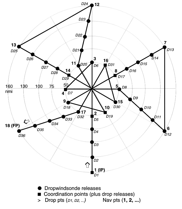
Subject to safety and operational constraints, takeoff time will be 1800 UTC, to coordinate with the NMC analysis cycle at 0000 UTC. The flight pattern for the dropwindsonde (upper) aircraft is shown in Fig. 1. During the ferry to the initial position (IP), the aircraft will climb to the 500 mb level (about FL 180) or above. The 400 mb level (about FL 250) should be reached as soon as possible and maintained throughout the pattern, unless icing conditions dictate a lower level for safety. dropwindsondes will be released at the indicated locations in Fig. 1, and pseudo-dual Doppler data will be taken during the three "figure 4" portions of the pattern. If there is active convection in the outer triangle portions of the pattern, Doppler data should be taken there as well. All drop and turn points in the pattern are relative to the moving center of the storm. Mandatory and significant level information from selected dropwindsondes will be transmitted in real time back to NMC and NHC.
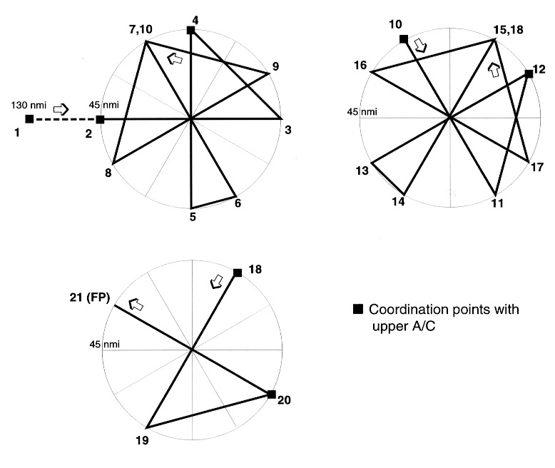
The flight pattern for the lower aircraft is given in Fig. 2. Subject to safety and operational constraints, the lower aircraft should take off first. Flight level for the lower aircraft will be FL 100. The lower aircraft will release no dropwindsondes. In order to ensure that true-dual-Doppler data are obtained, communication and coordination between the two aircraft are essential. Both aircraft must begin their patterns at their respective IP's simultaneously. Once the patterns are underway, all coordination maneuvers should be performed by the lower aircraft; except for changes in air-speed, the upper aircraft will fly its pattern as drawn. In addition to the IP's, the start of each inbound Doppler leg should be coordinated.
| Upper Aircraft Nav Point | Lower Aircraft Nav Point |
| 1 (IP) | 1 (IP) |
| 2 | 2 |
| 4 | 4 |
| 8 | 10 |
| 10 | 12 |
| 14 | 18 |
| 16 | 20 |
The lower aircraft is responsible for delaying to ensure that the CP's are reached simultaneously by both aircraft. The patterns are designed so that the lower aircraft will reach the CP's shortly before the upper aircraft; however, if necessary, the lower aircraft may cut the corners at points 9 and 17 in order to reach points 10 and 18 on time.
The lower aircraft at times may fly an optional "circle" pattern just outside the eyewall. This would occur just after the coordinated figure 4 pattern (i.e., immediately following nav points 5, 13, or 21 [Fig. 2]). The aircraft flies a nearly circular pattern (actually numerous short straight-line segments) just outside the eyewall while the tail radar scans in a fore/aft sequence. The circle must be as small as possible, since no data are obtained from the inner 40% (by radius) of the circle. The lower aircraft would re-coordinate with the upper aircraft at nav point 10 or nav point 18 (Fig. 2).
Special Notes:
The VME pattern can be coordinated with the Hurricane Surveillance Mission flown by the new NOAA G-IV jet aircraft. The VME pattern is unchanged while the G-IV drops sondes in the hurricane's large-scale environment.If a supplemental high-altitude aircraft (such as the NASA DC-8 or the NOAA G-IV) is available, it can participate in the experiment by flying the pattern shown in Fig. 3. This pattern should be flown at the highest possible altitude (presumably at least 39,000 ft) and dispense dropwindsondes at the indicated locations. Drops on the innermost radius (50 nmi) may have to be omitted due to traffic below.
Figures
- Upper aircraft flight pattern for VME experiment.
- True airspeed calibration is required.
- The pattern may be entered along any compass heading.
- During the ferry to the IP, aircraft will climb to the
500 mb level (about FL 180) or above. The 400 mb level (about
FL 250) should be reached as soon as possible and maintained
throughout the remainder of the pattern, unless icing or
electrical conditions require a lower altitude.
- The IP must be reached at the same time the lower aircraft
reaches its IP. Coordinating points must be reached
simultaneously with the lower aircraft. The lower aircraft is
responsible for delaying prior to the IP and CP's to ensure that
these points are reached simultaneously.
- There are no scheduled drops in the eye. It may be
desireable to make a drop during the second pass of each figure
4, assuming clearance from the lower aircraft and any USAF
reconnaissance aircraft. Allowable dropwindsonde drop
frequencies should be coordinated with USAF aircraft.
- Upwind turns are not required. Although aircraft turns
are not expected to affect dropwindsonde wind accuracy, we
expect to continue the practice of dropping after turns.
- Set airborne Doppler radar to continuously scan
perpendicular to the track on radial penetrations, and F/AST on
downwind legs, and on radial legs beyond 50 nmi (95 km) radius.
- Aircraft should not deviate from the pattern to find the wind center in the eye.
- Lower aircraft flight pattern for VME experiment.
Notes for Figure 1:
Instrumentation and expendables:
The Vortex Motion and Evolution experiment requires the standard set of flight-level sensors, the GPS AVAPS dropwindsonde system, and the Doppler radars. There are no requirements for special instrumentation. The two-aircraft mission requires :
- 40 dropwindsondes (including backups)
- 2 slow (flight-level data) tapes
- 10 radar DAT tapes
Tables
| Segment | Distance (nm) | GS (kt) | Time (:mm) | Total Time (h:mm) |
| 1-2 (CP) | 110 | 280 | :24 | :24 |
| 2-3 | 100 | 280 | :22 | :46 |
| 3-4 (CP) | 71 | 320 | :13 | :59 |
| 4-5 | 100 | 280 | :22 | 1:21 |
| 5-6 | 118 | 260 | :27 | 1:48 |
| 6-7 | 160 | 300 | :32 | 2:20 |
| 7-8 (CP) | 110 | 280 | :24 | 2:44 |
| 8-9 | 100 | 280 | :22 | 3:06 |
| 9-10 (CP) | 71 | 320 | :13 | 3:19 |
| 10-11 | 100 | 280 | :22 | 3:41 |
| 11-12 | 118 | 260 | :27 | 4:08 |
| 12-13 | 160 | 300 | :32 | 4:40 |
| 13-14 (CP) | 110 | 280 | :24 | 5:04 |
| 14-15 | 100 | 280 | :22 | 5:26 |
| 15-16 (CP) | 71 | 320 | :13 | 5:39 |
| 16-17 | 100 | 280 | :22 | 6:01 |
| 17-18 | 118 | 260 | :27 | 6:28 |
| Segment | Distance (nm) | GS (kt) | Time (:mm) | Delay (:mm) | Total Time (h:mm) |
| 1-2 (CP) | 85 | 250 | :20 | :04 | :24 |
| 2-3 | 90 | 250 | :22 | :46 | |
| 3-4 (CP) | 64 | 290 | :13 | :59 | |
| 4-5 | 90 | 250 | :22 | 1:21 | |
| 5-6 | 23 | 290 | :05 | 1:26 | |
| 6-7 | 90 | 250 | :22 | 1:48 | |
| 7-8 | 64 | 290 | :13 | 2:01 | |
| 8-9 | 90 | 250 | :22 | 2:23 | |
| 9-10 (CP) | 64 | 290 | :13 | :08 | 2:44 |
| 10-11 | 90 | 250 | :22 | 3:06 | |
| 11-12(CP) | 64 | 290 | :13 | 3:19 | |
| 12-13 | 90 | 250 | :22 | 3:41 | |
| 13-14 | 23 | 290 | :05 | 3:46 | |
| 14-15 | 90 | 250 | :22 | 4:08 | |
| 15-16 | 64 | 290 | :13 | 4:21 | |
| 16-17 | 90 | 250 | :22 | 4:43 | |
| 17-18(CP) | 64 | 290 | :13 | :08 | 5:04 |
| 18-19 | 90 | 250 | :22 | 5:26 | |
| 19-20(CP) | 64 | 290 | :13 | 5:39 | |
| 20-21 | 90 | 250 | :22 | 6:01 |
Data Management
Operational dropwindsonde data from selected drops will be transmitted in standard formats to NCEP, where the data are inserted into operationsal analyses and archived. Complete dropwindsonde datasets are recorded on the aircraft and are post-processed at HRD.
Management of Doppler and processed dropwindsonde data will be under the control of HRD. HRD will syntesize Doppler wind fields from the raw data, and HRD's multi-scaled objective analysis algorithm will be sued to assimilate the dropwindsonde, Doppler, flight-level and satellite data into three-dimensional objective analyses.
Funding
Flight-hours are supported by AOC base funds. Expendables are supported by HRD base funds.
Related Publications
Marks, F.D., Jr., R.A. Houze, Jr., and J.F. Gamache,1992: Dual-aircraft investigation of the inner core of Hurricane Norbert. Part I: Kinematic structure J.Atmos.Sci. 49 919-942
Houze, R.A., Jr., F.D. Marks, Jr., and R.A. Black,1992: Dual-aircraft investigation of the inner core of Hurricane Norbert. Part II: Mesoscale distribution of ice particles. J.Atmos.Sci. 49 943-962
Franklin, J.L., S.J. Lord, S.E.Feuer, and F.D. Marks, Jr., 1993, The kinematic structure of Hurricane Gloria (1985) determined from nested analyses of dropwindsonde and Doppler radar data.Mon.Wea.Rev. 121 2433-2451
Gamache, J.F. ,R.A. Houze, Jr., and F.D. Marks, Jr., 1993: Dual-aircraft investigation of the inner core of Hurricane Norbert. Part III: Water budget J.Atmos.Sci. 50 3221-3243