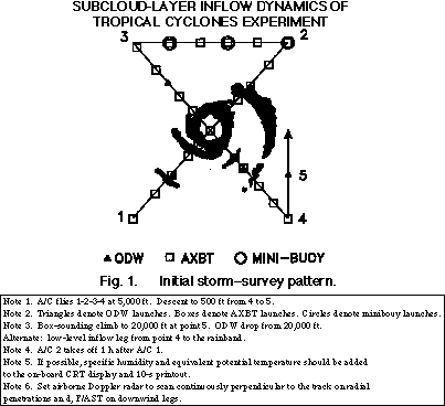
Phase I: Initial survey. Operation conditions permitting, the first aircraft (A/C 1) departs the base of operations 1 hour before the second aircraft (A/C 2). A/C 1 performs the storm survey. The nominal survey pattern is a figure-4 patt ern, where the aircraft finds the storm center, passing directly through the storm to the opposite side on the same heading. Minidrifter buoys, ODW's, and AXBT's are dropped as indicated in Fig. 1.
The survey pattern should extend 60-90 nmi from the storm center and preferably beyond any suitable rainband targets. A/C 1 then turns downwind, as in Fig. 1. At position 3, the aircraft again heads through the storm to the opposite side at point 4. By this time or before, the rainband target should have been selected. If the target can be selected after one pass through the storm, the figure-4 survey should be completed. On each pass into and out of the storm, an AXBT and an ODW are dropped between any rainbands and the eyewall, preferably in a precipitation-free region. AXBT's are also dropped on the outside of any rainbands encountered in the survey.
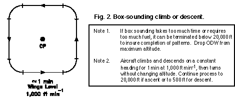
Phase II: Rainband structure. After the target has been chosen, A/C 1 proceeds to the initial point of the second phase, indicated by point 5 in Fig. 1, on the upwind outside end of the rainband target area. At point 5, A/C 1 performs a d eep sounding (Fig. 2), as clear as possible of cloud and precipitation, climbing from 500 to 20,000 ft, or as high as the aircraft will climb at that time.

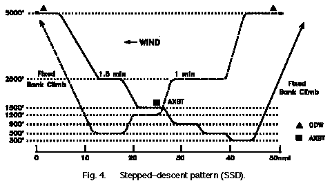
The aircraft then descends to 5,000 ft, where it begins a simultaneous stepped-descent (SSD) pattern, as illustrated in Fig. 3.
During this time, A/C 2 should be approaching the storm, also fixing the storm center, if the center is between the base of operations and the target rainband. ODW's should be dropped between the rainband and the eyewall. The second aircraft should arri ve at the rainband by the end of the A/C 1 stepped-descent pattern. If early, A/C 2 should attempt a box sounding on the inner side of the rainband from 500 to 10,000 ft. The aircraft should then assemble at points 5 (A/C 1) and 7 (A/C 2) to perform the simultaneous stepped descent pattern as shown in Figs. 3 and 4. Both aircraft should set airborne Doppler radars for fast scan and maintain a distance of 5 nmi from either edge of the 25-dBZ radar reflectivity contour.

Phase III: Investigation of boundary layer recovery. In some cases, the region between the eyewall and the major convectively active rainband may be characterized as a moat with suppressed convective activity and only light rain from the a nvil shield of the eyewall and rainband. If such a region exists on a cross-wind scale of >20 nmi, A/C 1 and A/C 2 will conduct detailed cross-wind (CW) profile patterns at >30 nmi separation, as depicted in Figs. 5 and 6.
These measurements will detect low equivalent potential temperature air and its recovery. The profile locations should maintain a fixed position relative to the storm center, but may be changed to stay in the clear.
If secondary rainbands exist in this region such that well-defined clear regions of >20 nmi scale are not present, A/C 1 will identify one or two target convective cells within the band for repeated Doppler box patterns as given in Fig. 7, with leg len gth s of <18 nmi and outside turns. The cells should be followed as they evolve along the band. A deep sounding should be executed at point 10 after the Doppler pattern. Upon completion, A/C 1 should return home through the storm center at 5,000 ft.
To complement the rainband momentum transport measurements of A/C 1, A/C 2 conducts a high-density ODW sampling pattern between rainbands in sequence 7-8-9-8-7-8-9, as shown in Fig. 7. Upon completion, A/C 2 returns home through the storm center at 5,000 ft altitude.